


0102030405
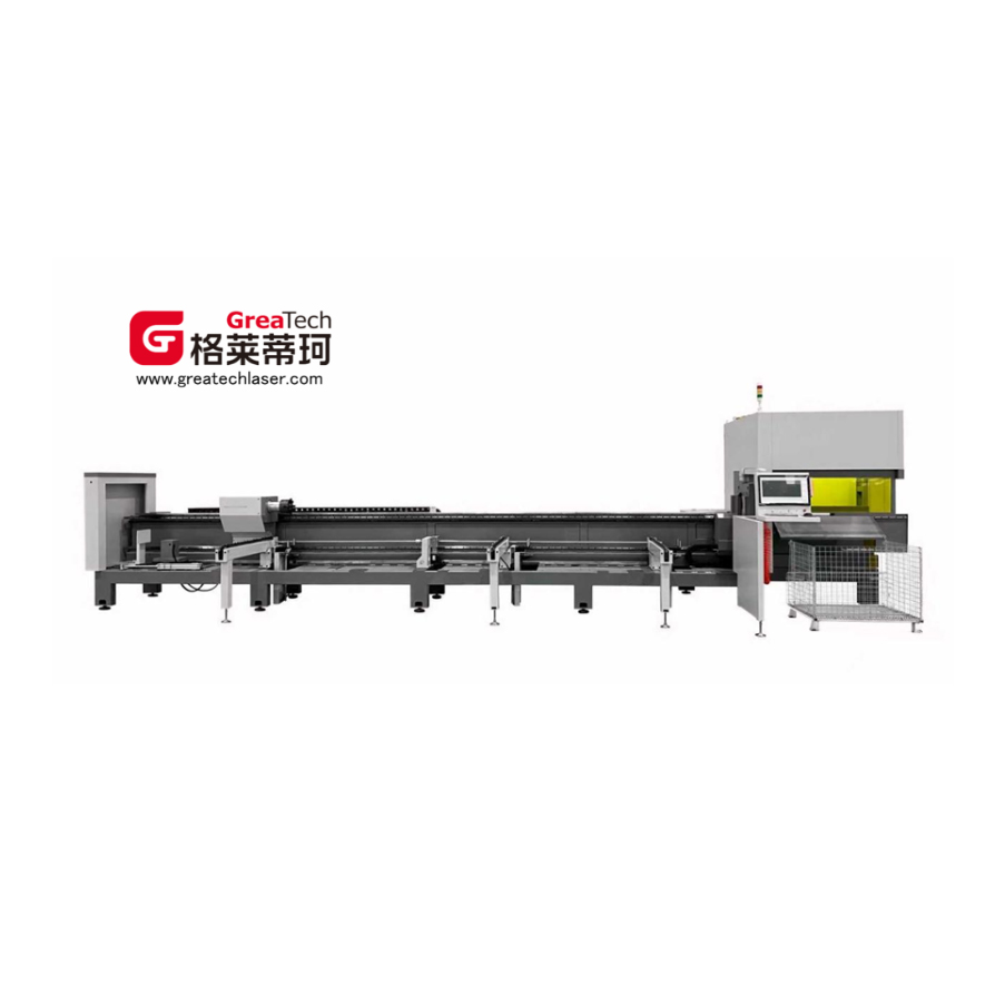
High-Speed Laser Pipe Cutting Machine G17-7013 from China Suppliers - Efficient, Low-Cost Factory Solution
Key Component Configuration
| Order No. | Component Name | Brand | Model / Origin |
| Key Components | |||
| 1 | Fibre Laser | Ricke | 2000W / Top-tier domestic brand |
| 2 | Cutting Head | BOCI | 2000W / Top-tier domestic brand |
| 3 | Gear Rack | Specialty: Taiwan | M2-6 class / Taiwan, China |
| 4 | Reduction Box | TECHMECH / Modori | 090 / Germany |
| 5 | Linear Guide Rail | SMAGIC, Taiwan | CGH30 / Japan |
| 6 | Motor | HuiChuan / HoChuan | High-performance motor, max speed 4000 rpm, bus-type configuration |
| 8 | Water Cooling Unit | Hanli / Teyu | Top-tier domestic brands |
| 10 | Electronic Control Element | Schneider, France | China |
| 11 | Airway Component | AIRTAC, Taiwan | China |
| Processing Components | |||
| 11 | Main Bed Frame | Self-developed, Suzhou | 9 meters / annealing at 600°C |
| 12 | Chucks (optional for 0 tailstock) | Self-developed, Suzhou | KDN-130 pneumatic / continuous air supply clamp |
| 13 | Auxiliary Feeding, Servo Floating Support Frame | Self-developed, Suzhou | 3 stents / 80 kg load-bearing capacity |
| 14 | Fully Automatic Feeding Device (optional) | Self-developed, Suzhou | 1.5-ton automatic continuous feeding of standard pipe for bundling |
| 15 | Material Feeding Device / Feeding Frame (optional) | Self-developed, Suzhou | 20 kg per meter, maximum cutting length 2.0 meters |
| Software System | |||
| 15 | Operating System | Shanghai Baichu | Bus System / Shanghai |
| 16 | Material Matching Software | Shanghai Baichu | 3D Tube Cutting Software / Shanghai |
| Other | |||
| 17 | Operation Direction | Left-hand car | Standard configuration |
| 18 | Packaging and Transportation | Standard packaging | Standard configuration |
⚡ Note: The industrial machine operates at 380±5V. Customers should install a voltage stabilizer based on actual conditions.


Component Technical Parameters
| Component Name | Attribute | Parameter Values |
| Laser | Output Power | 2000W |
| Work Pattern | Fiber continuous | |
| Fibre Diameter | 50μm | |
| Cooling Method | Hydrocooling | |
| Cuttable Material | Carbon steel, stainless steel, aluminum alloy, purple copper, brass, and other metals | |
| Lathe Bed | Structure | Tube sheet welding |
| Length | 8.5 meters | |
| Cartridge | Chuck Model | QL160 |
| Work Pattern | Pneumatic | |
| Bearing | 80 kG | |
| Cutting Head | Focal Length | 125 mm |
| Collinear Focal Length | 100 mm | |
| Focal Speed | 100 mm/s (manual focus not available) | |
| Auxiliary Air Pressure | ≤3 MPa | |
| Water Cooling Unit | Cooling Medium | Distilled water / Deionized water |
| Ambient Water / Frozen Water Settings | 30 / 20 (adjustable) | |
| Temperature Regulation Accuracy | ±0.1ºC | |
| Pump Capacity | 10 L/Min | |
| Pump Lift | 20 m |
Complete Machine Technical Parameters
| Class | Attribute | Parameter Values |
| Environment Attribute | Device Series | Small platform: 125 series |
| External Dimensions (mm) | 9600 × 3300 × 2300 | |
| Total Weight (tons) | Approximately 3.2 T | |
| Full Power Consumption (KW) | 20 ~ 25 | |
| Running Temperature (℃) | 0 – 40 | |
| Range of Work | Processing Path (mm) | Pipe diameter: 10–120 |
| Incision Width (mm) | 0.1–0.2 | |
| Y/X/Z/U Axis Stroke (mm) | 7000 / 150 / 250 / Unlimited rotation | |
| Resetting Accuracy / Speed | X/Y Axis Positioning Accuracy (mm) | ±0.03\1000 (7000±0.06) |
| X/Y Axis Repeatability (mm) | ±0.03 | |
| Cutting Accuracy | ±0.1 | |
| Rotation of X-axis Repeatability (arc minutes) | ≤5 | |
| Maximum Rotation Speed of X-axis (RPM) | 130 HuiChuan | |
| Velocity and Acceleration | Maximum Acceleration of X/Y Axis | 1.5G |
| Maximum Idle Speed on X-axis (m/min) | 100 | |
| Maximum Idle Speed of Y-axis (m/min) | 130 HuiChuan | |
| Feed Parameters | Manual Feeding (mm) | 3000–7000 |
| Automatic Feeding Length (mm) | 5800~6450 (non-standard models may range from 5000~7000) | |
| Cycling Feed Cycle (s) | Initial loading ≤50, subsequent loading ≤20 | |
| Loading Machine Capacity (kg) | Semi-automatic: 200; Fully automatic: 1500 | |
| Maximum Load Capacity (kg) for Single Pipe in Manual Feeding | 80 | |
| Maximum Load Capacity (kg) for Single Pipe in Automatic Feeding | 80 | |
| Cutting Parameters | Tail Length (mm) | External clamp 45 (internal clamp 20) (optional with 0 tailstock) |
| Minimum Cutting Length (mm) | Standard 2500 |
* The above technical specifications were established through testing on March 1, 2025.
Key Components and Motion Control
1. Bed Frame
The main body of the device is fabricated using sheet metal and pipe welding processes. After welding is completed, the entire machine is sent to a heat treatment furnace for high-temperature annealing at 600°C and held at a constant temperature for 4.5 hours. It is then slowly cooled to 200–300 degrees Celsius in the furnace before being removed for natural air cooling, thereby fully eliminating internal residual stresses generated during welding and processing. The process flow first involves rough machining to remove most of the allowance, followed by precision finishing processes, which can significantly improve the overall rigidity and structural stability of the machine tool, ensuring stable and reliable machining accuracy during long-term operation. The entire machine adopts a side-mounted layout structure and is equipped with an integrated automatic feeding system, which not only effectively improves the efficiency of material conveying and loading but also simplifies the operations of workpiece loading/unloading and material transfer.
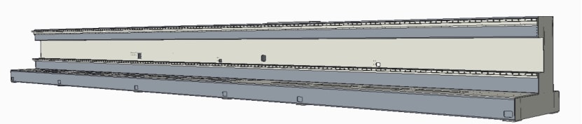
The main structure of the bed is formed by integral welding of plates and pipes, with additional multiple sets of reinforcing rib plates and tubular reinforcing plates for composite reinforcement. Through optimizing the vertical and horizontal layout design, the overall structural rigidity of the equipment in both horizontal and vertical directions is effectively improved, significantly enhancing the anti-deformation and anti-vibration capabilities. This ensures that the equipment remains stable under long-term heavy-load operating conditions, is not prone to deformation, and guarantees processing accuracy and service durability.
1.2 Welding Process
All key welds strictly follow standardized welding specifications, with welds on both sides arranged evenly, using symmetric and staggered welding processes. This process can evenly disperse welding stress, minimize thermal deformation and residual stress generated during welding, avoid defects such as bed warpage and distortion, and improve welding forming quality and structural consistency.
Annealing Treatment Report
Each bed is managed with individual independent traceability, corresponding to a unique body number, and is equipped with a complete and traceable professional annealing inspection report. The welding residual internal stress is eliminated through stress relief annealing process, and a full set of compliant quality inspection documents are retained to meet the requirements of quality acceptance and file retention.
2. Crossbeam and X-axis / Z-axis Devices
2.1 Crossbeam Structural Processing and Safety Protection
The equipment crossbeam is subjected to professional high-temperature annealing treatment in the manufacturing process. This process can effectively eliminate residual internal stresses generated during raw material processing, cutting and welding procedures, avoiding structural deformation, bending or cracking caused by stress release in subsequent long-term operation. By virtue of stress relief treatment, the crossbeam maintains excellent structural rigidity and dimensional stability at all times, which further ensures the precise running accuracy and long-term service stability of all moving components matched with the laser head. In the actual working state, electrical limit switches are installed on the stroke path to accurately control the effective moving travel of the mechanism and realize precise positioning control. Meanwhile, elastic buffer pads are fixedly arranged at both ends of the moving track to form physical mechanical limiting protection. The dual protection of electrical limiting and mechanical buffering can effectively prevent over-travel impact and collision faults.
2.2 Functional Design and Driving Control of Z-Axis Mechanism
The core function of the Z-axis motion mechanism is to realize stable and accurate vertical lifting and lowering movement of the laser processing head, so as to adapt to different processing heights, focus adjustment and workpiece processing requirements of different thicknesses. The whole vertical motion action is intelligently controlled by the numerical control (CNC) system: the system sends out motion instructions to drive the high-precision servo motors to operate synchronously, and the servo motors transmit power to the linear driving execution components. Driven by the linear actuators, the Z-axis sliding seat mounted with the laser head performs reciprocating up-and-down linear displacement along the precision guide rail. High-sensitivity proximity induction switches are configured at the upper and lower limit positions of the Z-axis respectively to quickly sense the position of the slider and feed back signals in real time, strictly limiting the vertical moving range of the mechanism and guaranteeing the continuous, safe and highly reliable operation of the Z-axis transmission mechanism.
3. Cutting Head and Following Part
3.1 Real-time Monitoring of the Sealing Status in the Protected Area
The equipment can conduct all-weather real-time online monitoring of the sealing conditions in the protected area, accurately identify issues such as seal leakage and abnormal air tightness, and issue timely warnings. This function can significantly optimize the internal dust-proof, anti-pollution, and anti-oxidation effects, effectively slow down the process of pollutant erosion, significantly extend the overall service life of the protective lenses, and at the same time ensure the stability of the equipment during long-term continuous operation, helping the production line achieve continuous and stable processing and reducing the risk of unplanned downtime.
3.2 Impact-resistant Integrated Cutting Head Structural Design
The cutting head adopts a highly reliable impact-resistant protective structure, which greatly upgrades the physical protection performance, significantly reduces the probability of equipment failure and the rate of return for repairs, and fundamentally eliminates the cumbersome process of on-site maintenance by manufacturers. The accessory disassembly and assembly structure has been optimized in a user-friendly manner, making the operation simple and easy to understand. Customers can independently and quickly complete component replacement and simple maintenance, which greatly shortens the shutdown maintenance time and effectively reduces the comprehensive use costs such as later labor and operation and maintenance.
3.3 Additional Dust-proof Cover Protection Configuration for Optical Lenses
A special dust-proof cover is additionally installed in the key area of the core optical lens to form a double airtight protective barrier, further improving the sealing protection level of the core cavity and isolating impurities such as dust, water mist, and debris from entering the internal optical space. It avoids loss problems such as lens contamination, wear, and scratches, comprehensively protects core optical components, effectively extends the service life of core lenses, and ensures the purity of optical path transmission and processing accuracy.
3.4 High-precision Capacitive Sensing Automatic Following Control System
The system is equipped with a standard high-precision capacitive sensing automatic tracking module, which relies on intelligent algorithms to achieve precise closed-loop control. It can drive the Z-axis to complete highly stable floating following actions, adjust the cutting height in real-time and adaptively, effectively avoid height error problems caused by factors such as material thermal stress deformation, uneven pipe surface, and workpiece deviation during the cutting process, stabilize the cutting focus position, improve cutting forming quality and processing consistency, and adapt to the efficient production needs under complex working conditions.
5. Cooling System
This system is equipped with the domestically renowned brand Hanli's professional laser water chiller, which features excellent operational stability, high temperature control precision, and strong adaptability. The entire machine is equipped with a dual independent temperature control system, which can precisely adjust the temperature of the laser and the cutting head in separate zones. This effectively ensures the stable output of the laser light source, while maintaining the cutting head within the optimal operating temperature range, significantly improving the processing reliability and service life of the entire machine. The water chiller integrates multiple safety protection functions, including water pressure abnormality alarm, high and low temperature over-limit alarm, voltage fluctuation alarm, and various fault self-inspection alarms.
Specific Parameters of Laser Special Cooling System
| Double Temperature and Double Control Laser Special Chiller | |
| Power Input | 220V / 50HZ |
| Cooling Medium | Distilled water / Deionized water |
| Water Temperature Control Accuracy | ±0.1ºC |
| Set to Room Temperature Water | Standard 30°C (adjustable) |
5. Electrical Control System (Bachu Bus)
The electrical control system of the optical fiber tube cutting machine is the core functional unit that governs the overall operation, motion control and parameter adjustment of the equipment, which is mainly composed of three indispensable core components, namely the Bachu numerical control (CNC) system, high-precision servo system and standardized low-voltage electrical system. At the heart of the entire control solution lies the high-performance Bachu CNC system. Adopting a mature Windows-based PC numerical control platform, this system stands out in the industry for its outstanding advantages such as ultra-fast interpolation calculation speed, powerful data processing capability and humanized interactive operation interface. It can efficiently complete complex path planning and real-time operation instructions, greatly improving the cutting accuracy and processing efficiency of the optical fiber tube.
In terms of the servo drive part, the servo system is equipped with imported brand AC servo motors and matching dedicated drivers. This configuration ensures excellent operating stability, sensitive dynamic response speed, strong overload resistance and large load-bearing capacity during the long-term continuous working process of the machine tool. Furthermore, the optical fiber tube cutting machine is ingeniously equipped with multifunctional soft key components. These soft keys support personalized customized function settings under a variety of different processing and operation modes, effectively reducing the number of traditional physical buttons on the control panel. All preset and real-time operational functions of the equipment are intuitively presented through a visualized hierarchical menu interface, enabling operators to quickly view working status, switch functions and adjust parameters.
5.1 CNC System
In terms of the servo drive part, the servo system is equipped with imported brand AC servo motors and matching dedicated drivers. This configuration ensures excellent operating stability, sensitive dynamic response speed, strong overload resistance and large load-bearing capacity during the long-term continuous working process of the machine tool. Furthermore, the optical fiber tube cutting machine is ingeniously equipped with multifunctional soft key components. These soft keys support personalized customized function settings under a variety of different processing and operation modes, effectively reducing the number of traditional physical buttons on the control panel. All preset and real-time operational functions of the equipment are intuitively presented through a visualized hierarchical menu interface, enabling operators to quickly view working status, switch functions and adjust parameters.
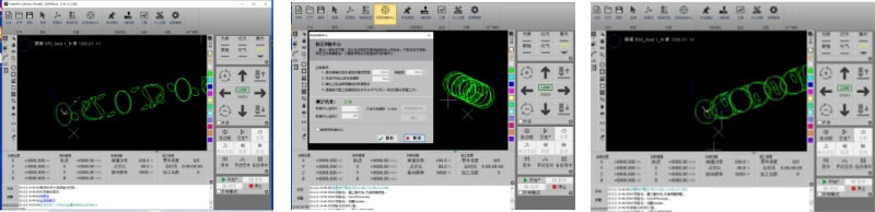
The electrical control system of the optical fiber tube cutting machine is the core functional unit that governs the overall operation, motion control and parameter adjustment of the equipment, which is mainly composed of three indispensable core components, namely the Bachu numerical control (CNC) system, high-precision servo system and standardized low-voltage electrical system. Adopting a mature Windows-based PC numerical control platform, this system stands out in the industry for its outstanding advantages such as ultra-fast interpolation calculation speed, powerful data processing capability and humanized interactive operation interface. It can efficiently complete complex path planning and real-time operation instructions, greatly improving the cutting accuracy and processing efficiency of the optical fiber tube. In terms of the servo drive part, the servo system is equipped with imported brand AC servo motors and matching dedicated drivers. Furthermore, the optical fiber tube cutting machine is equipped with multifunctional soft key components supporting personalized customized function settings, simplifying the overall structural layout of the panel. All preset and real-time operational functions are intuitively presented through a visualized hierarchical menu interface, realizing simple, convenient and intuitive daily operation.
5.3 Other Functions of the CNC System
- Surface height tracking control of pipe (following function)
- Undo
- Breakpoint return function
- Find Edge
- Suture compensation function
- Pulse cutting control function
- Frog jump function
- Import multiple parts
- Layout
- Quick conversion and batch processing
- Efficient automatic formatting
- The corresponding process database can be configured according to different materials and thicknesses
- Outline detection and graphic optimization processing
- Auto-optimize cutting path
- Perfect expert craftsmanship with flexible manual process adjustment
- Supports labeling and small hole marking
- Microconnect
- Weld compensation
The NC system of the machine has the function of self-checking and alarm and automatic protection, and the external condition has the function of alarm display and automatic protection.
6. Low-voltage Electrical System
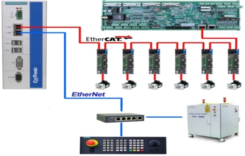
The low-voltage electrical system is located inside the electrical control cabinet, serving as the interface for the entire electrical control system. All components required for the electrical control system, including power supplies, relays, circuit breakers, contactors, and servo drive systems, are installed within the electrical control cabinet. The motor used is a bus motor, which reduces the number of wiring lines.
Connection diagram
Water, Electricity and Gas Demand
⚡ Electricity Demand
| Electricity Demand | Related Data | Notes |
| Three-phase five-wire 380~400VAC/50Hz distribution box | 380V±2% / 50Hz |
1. If voltage fluctuation exceeds 5%, a voltage stabilizer should be installed. A three-phase five-wire power supply of at least 45KVA is recommended. 2. The three-phase power supply must maintain an imbalance below 2.5% (Note: The 400VAC/50Hz/380V±2%/50Hz voltage must not experience sudden surges or power outages, as these may damage the laser). 3. The diameter of a single cable wire shall not be less than 10 square. 4. The power supply must be effectively grounded with a resistance ≤3Ω. 5. Three circuit breaker interfaces are required for the cutting machine wiring. |
| Cooling Water Requirement | Related Data | Notes |
| Chiller Water | Distilled water / Deionized water | 30L, conductivity less than 10 μS |
| Protective Gas Demand | Related Data | Notes |
| Oxygen | Purity: ≥99.6% Gases with purity below 99.6% may affect the cutting performance and quality. |
Cutting carbon steel and various iron plates with oxygen-assisted cutting achieves high-quality and efficient results. |
| Pressure: 1 MPa Flow rate ≥ 1 m³/min |
||
| Nitrogen | Purity: ≥99.99% Gases with purity below 99.99% may adversely affect cutting performance and quality. |
Cutting of stainless steel and galvanized sheets is performed with nitrogen-assisted cutting, achieving high-quality results. |
| Pressure: 2.5 MPa Flow rate: ≥2.5 m³/min |
||
|
1. Bottled gas requires the installation of a pressure reducing valve for the cylinder. 2. Oxygen (O₂) pressure reducing valve: The adjustable outlet pressure range is 0.4 MPa to 1.2 MPa, with a pressure fluctuation range of 1%. 3. Nitrogen (N₂) pressure reducing valve: The adjustable outlet pressure range is 0.4 MPa to 5 MPa, with a pressure fluctuation range of 1%. |
||
| Air | Working pressure ≥1.3 MPa |
1. If air cutting is required, the user shall provide a compressor, refrigerated dryer, air receiver, and four-stage filtration (filtering precision 0.01 microns). 2. The gas in the air-to-laser cutting machine must be free of water and oil, as these contaminants may compromise cutting quality and reduce the lifespan of various lenses. 3. The condensation point temperature must not exceed 5°C. 4. Oil content ≤0.003 ppm, solid particles ≤0.01 μm |
| Flow rate ≥ 1.8 m³/min | ||
| Installation Environment | Related Data | Notes |
| Temperature Requirement | 5 ~ 30°C | The simple laser should be placed in a separate air-conditioned isolation room. |
| Humidity Requirements | <70% | |
| Foundation Requirements | Site levelling; No strong vibrations |
1. In case of strong vibrations, additional anti-vibration grooves should be installed. 2. The foundation must ensure sufficient strength and must not allow settlement. 3. Install the foundation according to the foundation installation drawings provided by our company. |
| Note: The equipment placement area must have good ventilation conditions, be free from dust, corrosion, and leakage. The control cabinet and laser are the core components of the equipment, and exposure to devices such as arc welding and discharge machining machines should be avoided. Electromagnetic interference from the equipment must be avoided to prevent interference with its normal operation. | ||
Frequently Asked Questions (FAQ)
Q
What materials can the laser tube cutting machine cut?
The machine is capable of cutting a wide range of metal materials, including carbon steel, stainless steel, aluminum alloy, purple copper (red copper), brass, and other metal pipes and tubes. The 2000W fiber laser ensures efficient and precise cutting across all these materials.
Q
What are the power supply requirements for this laser tube cutting machine?
The machine requires a three-phase five-wire power supply at 380V±2% / 50Hz with a minimum capacity of 45KVA. Voltage fluctuation must not exceed 5%; if it does, a voltage stabilizer must be installed. The power supply must be effectively grounded with a resistance ≤3Ω, and the cable wire diameter must not be less than 10 square millimeters.
Q
What is the maximum pipe diameter and cutting length this machine can handle?
The machine supports pipe diameters ranging from 10 mm to 120 mm. The Y-axis stroke is 7000 mm, and the automatic feeding length ranges from 5800 mm to 6450 mm (non-standard models may support 5000 mm to 7000 mm). Manual feeding supports lengths from 3000 mm to 7000 mm, with a minimum cutting length of 2500 mm (standard).
Q
What type of cooling water is required, and how much is needed?
The chiller requires distilled water or deionized water with a conductivity of less than 10 μS. Approximately 30 liters of water is needed. The dual independent temperature control system maintains the laser and cutting head at their optimal operating temperatures with a precision of ±0.1ºC.
Q
What gases are required for cutting, and what are the purity requirements?
For cutting carbon steel and iron plates, oxygen (O₂) with a purity of ≥99.6% and a pressure of 1 MPa is used. For cutting stainless steel and galvanized sheets, nitrogen (N₂) with a purity of ≥99.99% and a pressure of 2.5 MPa is required. Air cutting is also supported, provided the user supplies a compressor, refrigerated dryer, air receiver, and four-stage filtration system (filtering precision 0.01 microns).
Q
What are the key installation environment requirements for this machine?
The installation environment should maintain a temperature between 5°C and 30°C and humidity below 70%. The floor must be level with no strong vibrations; if vibrations are present, anti-vibration grooves must be installed. The area must have good ventilation and be free from dust, corrosion, and leakage. The control cabinet and laser should be kept away from arc welding machines and discharge machining equipment to prevent electromagnetic interference.